Powerelements Technology
Powerelements Technology
All about the Powerelement
The high current contact is the direct interface to the printed circuit board and an important component of power electronics. For each application, the high current contact, the printed circuit board and the contacting method must be optimally matched. Discover all technological aspects of our Powerelements here!
In a trend-setting move, Würth Elektronik ICS has launched the lead-free product line LF Powerelements. All design guidelines and reliability aspects described here apply to the Original Powerelements as well as to the new and lead-free product line LF Powerelements.

Processing instructions & connection examples for Powerelements

Processing instructions for (LF) PowerOne
- Use only suitable press-in tools for pressing in.
- For Powerelements with bolt, the top punch must be recessed by the length of the bolt. Do not apply pressure to the bolt.
- It is recommended to leave a gap of 0.5 mm between the PCB and the base of the bolt.
- For Powerelements with a flat surface, a simple, full-surface top punch is sufficient.
- For angled Powerelements, the top punch must be L-shaped. The larger surface area must be selected for the press-fit process.

Processing instructions for (LF) PowerTwo
- Use only suitable press-fit tools for press-fitting.
- A 0.5 mm gap between the PCB and the bolt base is recommended.
- For the two-piece (LF) PowerTwo high current contacts, the press-fit element must be pressed into the PCB first.
- When fastening the press-in element, it must be supported to prevent the base element from being pressed out.
- The press-in element must not protrude beyond the connection surface of the base element.
- The press-in element is not intended for contacting components or for supplying current.

Processing instructions for LF PowerPlus 1.0
- Use only suitable press-in tools for pressing in.
- For LF PowerPlus 1.0 Powerelements with threaded bolt, the top punch must be recessed by the dimension of the threaded bolt.
- Do not apply pressure on the screw mounting surface and the threaded bolt.
- It is recommended to leave a gap of 0.5 mm between the PCB and the base of the bolt.
- For 3.2 mm PCBs, the holes must be larger (refer to the hole pattern).
- For double-sided use, the smaller Powerelement must be pressed in first.

Processing instructions for LF PowerPlus 2.0
- Use only suitable press-in tools for pressing in.
- For LF PowerPlus 2.0 Powerelements with threaded bolt, the top punch must be recessed by the dimension of the threaded bolt.
- Do not apply pressure on the screw mounting surface and the threaded bolt.
- It is recommended to leave a gap of 0.5 mm between the PCB and the base of the bolt.
- For 3.2 mm PCBs, the holes must be larger (refer to the hole pattern).
- For double-sided use, the smaller Powerelement must be pressed in first.

Processing instructions for LF PowerBasket
Press-fit design:
- Use only suitable press-in tools for pressing in.
- For Powerelements with a flat surface, a simple, full-surface top punch is sufficient.
- It is recommended to leave a gap of 0.5 mm between the PCB and the base of the bolt.
SMT design:
- During processing, the basket is inserted through the PCB and soldered, which is also optimal for the positioning accuracy of the mating system.
- To protect the contact system during assembly, mating is done through the basket.

Processing instructions for PowerLamella
- Use only suitable press-in tools for pressing in.
- For Powerelements with a flat surface, a simple, full-surface upper punch is sufficient.
- It is recommended to leave a gap of 0.5 mm between the PCB and the base of the bolt.

Processing instructions for PowerRadsok
- Use only suitable press-in tools for pressing in.
- For Powerelements with protruding lamella, the top punch must be recessed around the lamella. Do not apply pressure to the lamella.
- It is recommended to leave a gap of 0.5 mm between the PCB and the base of the bolt.

Processing instructions for PowerFlex
- Use only suitable press-fit tools for press-fitting
- For Powerelements with bolt, the top punch must be recessed by the length of the bolt. Do not apply pressure to the bolt.
- For Powerelements with a flat surface, a simple full-surface upper punch is sufficient.
- It is recommended to leave a gap of 0.5 mm between the PCB and the base of the bolt.

Processing instructions for PowerBusbar PCB
- Press the PowerBusbar PCB busbars together with Würth Elektronik ICS Powerelements onto the PCB in a single operation. The recommended assembly sequence is Powerelement – PCB – busbar.
- No special press-fit devices are required for the prototype assembly, a simple toggle press is sufficient.
- The PCB and busbar must be supported and positioned in relation to each other during the press-fit process.
- The Powerelement must first be pressed into the PCB and then into the busbar.
- The electrically and mechanically effective connection of the pin (= pin length without chamfer) to the busbar must be at least 1 mm.
- The press-in force is applied at a 90° angle to the PCB.
- The through-hole plating of the PCB must be carried out according to our specifications.
- Only use suitable press-fit tools.
Note on the use of fastening materials

For processing Powerelements, we recommend standard nuts with additional washers, integrated washers, serrated locking nuts (serrated flange nuts) or planar flange nuts without serration made of stainless steel. Self-locking nuts (lock nuts) are not recommended; they are not permitted for LF PowerPlus.
Current carrying capacity
In a connector, the contact partners (pin and bush) are clearly defined. Typically, a contact system is selected to match the current carrying capacity of the connected cables. Wire cross-sections and permissible currents are therefore specified by standards. Powerelements do not have a mating connector. The "mating connector" is virtually the printed circuit board with its individual layout.
Note: The current carrying capacity must always be considered in the context of the overall system!
The current carrying capacity of the Powerelement to be achieved is influenced by several factors. The most important factors are the layout of the PCB, the prevailing environmental conditions of the overall system and the correct selection of the Powerelement.
Influencing factors of current carrying capacity
Implementation layout
- Wire cross-sections (conductor width and copper thickness)
- CU structure in the printed circuit board
- Positioning of the Powerelement
- Through-hole plating/ Vias
Powerelement
- Press-in and solder element
- Material selection
- Dimension of the Powerelement
- Number of contact points (pins)
- Dimension of the soldering and screw-on surfaces
Environmental conditions
- Operating temperature range
- Load currents
- Load intervals
- Thermal management/ cooling (active / passive)
- Allowable limit temperature
- Dimensioning of supply lines (cables, busbars etc.)
Qualification
- Determination of current carrying capacity according to DIN EN 60512-5-2
- ICS specific test environment
- Derating curve with reduction factor of 0.8 to the current value of the base curve

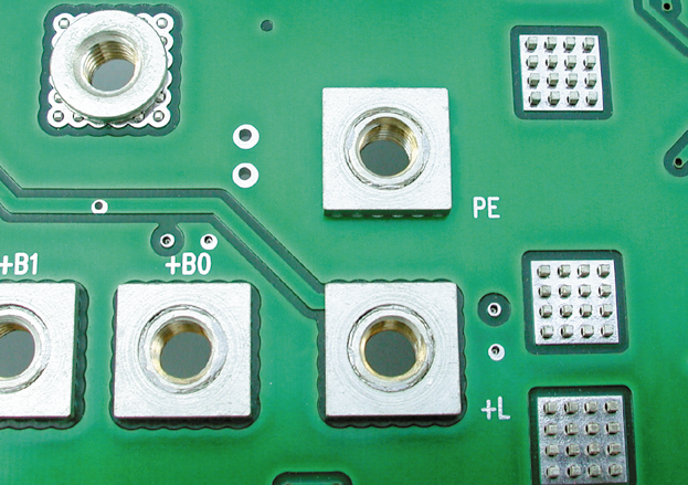
In the layout, the current carrying capacity is significantly influenced by the available copper cross-section, which is provided by the track width, the copper thickness, and the copper structure in the PCB in the form of multiple layers. The position of the Powerelement in the conductive pattern also influences the current carrying capacity (see figure).
If high currents are to be fed into the PCB, the positioning of the Powerelement in the layout plays an important role. The schematic illustration shows that the load capacity is significantly reduced if the element is positioned on the edge or even in the corner of a conductive area. A Powerelement with an edge dimension of 13x13 mm should be designed with a copper surface all around, this acts as a heat sink.
The position of the Powerelement must be chosen in such a way that the current can flow in all directions without resistance-increasing bottlenecks (avoid corners and edges). In the case of SMD components, a sufficient number of vias must be provided to distribute the current. The operating temperature range must be considered for the environmental conditions. At low ambient temperatures, higher loads are possible before the Powerelement temperature limit is reached. Conversely, operation at high ambient temperatures results in lower load currents.
The effective current carrying capacity is determined by the applied load currents and the load interval that causes the entire system to heat up. Short load intervals with peaks that are a multiple of the rated current have no effect if the permissible temperature limit for the Powerelement is not exceeded.
Good thermal management can further increase the possible current carrying capacity. If the resulting current heat is reduced by active cooling, higher load currents are possible before the allowable temperature limit is reached.
The allowable temperature limit has a decisive influence on the current carrying capacity that can be achieved. The higher it is, or can be, selected, the higher the load that can be placed on Powerelement.
The supply lines must be adequately dimensioned. They influence the thermal management and thus the achievable current carrying capacity. The choice of Powerelement also influences the current carrying capacity and must be adapted to the application. Another influencing factor is the assembly method. The choice of press-fit or solder element affects the contact resistances and the current distribution in the layers. In addition, the right choice of material minimizes power dissipation.
The dimensions of the Powerelement with the number of contact points and the dimensioning of the soldering and connection surfaces to the PCB and to the application also have a decisive influence on the contact resistances that can be achieved and thus on the current carrying capacity.
When qualifying the Powerelements, the current carrying capacity is determined in according to DIN EN 60512-5-2 and a derating curve is derived. The derating curve contains a reduction factor of 0.8 on the current value of the base curve. The information on current carrying capacity given at Würth Elektronik ICS always refers to a specific test environment. A much higher current carrying capacity can be achieved by implementing this in the overall system.
More information about the qualification of Powerelements can be found here.
FAQs about current carrying capacity
Massive press-fit technology is characterized by the fact that a cold weld is created during the press-fit process. A brief overload of several times the nominal current has no effect on the properties of the press-fit zone.
Example: In the product overview of the PowerOne Powerelement, a value of 1000 A is given. This is to indicate that the press-fit connection is generally not the limiting factor. Such a high current is quite feasible. An 8-layer PCB with 105 µm made of TG170 material and a corresponding layout design allows this value.
The conditions on the connection side are also varied. For example, an M8 threaded stud can be used to attach a cable lug for cross-sections from 6 to 95 mm², a busbar can be placed on top, or a component such as a MEGA fuse can be connected. The current carrying capacity of power supply elements must therefore always be considered in the context of the overall system. The many influences cannot be reduced to a binding specification of a current carrying capacity based on individual Powerelements. The information provided by Würth Elektronik ICS for the Powerelements therefore always refers to a purely specific test environment. Under these conditions a statement about the current carrying capacity is made, and a derating curve is derived. However, this does not in any way mean that this is the maximum possible current carrying capacity. With correct application, a much higher current carrying capacity is possible.
Derating Curve – What is it?

Derating means load reduction. In the context of electromechanical connections, a derating curve therefore describes by how much the current carrying capacity decreases with increasing ambient temperature while the limit temperature remains constant.
The figure shows derating curves for various PowerOne Powerelements. The connection on two wide 70 µm PCB layers allows 300 A at 20 °C ambient temperature for an element with 20 pins all around. This assumes that a sufficient cable cross-section is connected. The curves end at 125 °C, the so-called glass transition point of the standard FR4 PCB material. If a material with a higher value is selected, e.g. TG170, the curves shift to higher temperatures and end at approx. 170 °C. At an ambient temperature of 20 °C, currents significantly higher than 300 A are possible.
We will be happy to provide you with further derating curves for other product groups – Request now!
Mechanical stability
The mechanical stability of the overall system to be achieved is influenced by several factors. The most important factors are the layout of the PCB, the prevailing environmental conditions on the overall system and the correct selection of the Powerelement.
Influencing factors of mechanic stability
Implementation layout
- Wire cross-sections (conductor width and copper thickness)
- CU structure in the printed circuit board
- Positioning of the Powerelement
- Through-hole plating/ Vias
Powerelement
- Press-in and solder elements
- Material selection
- Dimension of the Powerelement
- Number of contact points (pins)
- Dimension of the soldering and screw-on surfaces
Environmental conditions
- Installation location
- Static and dynamic load
- Strain relief
Qualification (according to Würth Elektronik ICS specifications)
- Insertion and extraction forces
- Insertion and withdrawal forces
- Torques
- Shear forces / torsional loads
- Holding forces before and after vibration according to various standards
The footprint and pinout must be designed according to the manufacturer's specifications in order to achieve optimum retention forces. Refer to the product overviews for more information. PCB thicknesses from 1.5 mm or greater are recommended to ensure sufficient strength of the press-fit elements. The shear connection must be sized according to the stresses to which it will be subjected, taking into account the material of the Powerelement. Any swinging of cables or fastening elements between the Powerelements must be prevented by means of fixings.
In the case of the Powerelements, we have adjusted the number of pins or the solder surfaces so that the holding forces are sufficient for the intended use in all assembly methods.
Plug-in systems are more sensitive to vibration than screw connections.
Among other things, the environmental conditions of the installation site must be taken into account. Applications with dynamic loads place greater stress on the joints than static installation conditions. The load profile prevailing at the installation location must also be considered. Fixings and strain reliefs must be considered at the installation location in order to minimize vibrations on the assembly and thus on the Powerelements.
During Powerelement qualification, several tests are performed to determine the mechanical stability. For example, the press-in and press-out forces are tested for press-fit Powerelements, and the insertion and extraction forces are tested for plug-in Powerelements. Torque tests confirm that the specified torques are achieved with the material used. Shear and torsional loads confirm that SMD Powerelements are held securely to the PCB. SMD high current contacts can be loaded with the same torque as press-fit or THT-soldered Powerelements. To verify mechanical stability, various tests such as vibration, mechanical and thermal shock are performed according to various standards. For more information on Powerelement qualification, click here.
Torques

Powerelements are used for the connection of large surfaces and for the transmission of high currents in printed circuit boards. To avoid mechanical destruction of the elements, the maximum permissible torques must be observed. These differ from the standard fasteners used due to the material. The maximum torque is not applied in the press-fit zone, but on the nut thread or threaded bolt. The following table does not take into account different material combinations or thread lengths for bushes. Depending on the thread length, bushes can be tightened to higher torques.
| Thread size | Maximum permissible torque [Nm] * | Determined break torque [Nm] * |
|---|---|---|
| M3 | 0.5 | 1.5 |
| M4 | 1.2 | 4.0 |
| M5 | 2.2 | 6.0 |
| M6 | 3.9 | 10.0 |
| M8 | 9.0 | 17.0 |
| M10 | 17.0 | 32.5 |
| Thread size | Maximum permissible torque [Nm] * |
|---|---|
| M5 | 3.9 |
| M6 | 5.9 |
| M8 | 16.0 |
* The maximum allowable torques must be observed in order to avoid mechanical destruction of the components and the printed circuit board.
Guide values for mechanical properties
- Material: Brass
- Surface finish: Sn
- Shear strength: 350 N/mm²
- Tensile strength: 480 N/mm²
- Yield strength: 340 N/mm²
- Elongation: 20 %
- Modulus of elasticity: 96 kN/mm²
- Torsional modulus: 32 kN/mm² (shear modulus)
- Torque loads of 1 Nm / pin will destroy the press-fit pins.
- There are no significant forces in the press-fit area. The bolt or thread is damaged before the cold weld is destroyed.
All these features make the Powerelements in massive press-fit technology from Würth Elektronik ICS the first choice. Especially when high currents are applied in and robustness or durability are required.
Qualification

Our products are mostly customized solutions developed for different applications and operating conditions. They are extensively tested by customers under real conditions during the development and prototyping phase and undergo several qualification programs prior to series production.
The tests are performed by independent external test laboratories, by our customers or internally in our test laboratory. The following overview shows a selection of the successfully completed tests and qualified operating conditions that confirm the robustness and reliability of the press-fit technology.
Our qualification procedures
ISO 16750 Road vehicles - Environmental conditions and tests for electrical and electronic equipment
- IEC60068-2-6 Oscillations sinusoidal
- IEC60068-2-27 Shocking and -29 Continuous shocking
- IEC60068-2-32 Free fall
- IEC60068-2-64 Vibration broadband noise
- IEC60068-2-80 Mixed-mode vibration test
IEC60068-2-1 Cold and -2 Dry heat
IEC60068-2-11 Salt spray and -52 Salt spray cyclic
IEC60068-2-14 Change of temperature
IEC60068-2-30 Humid heat cyclic and -78 constant
IEC60068-2-38 Temperature/humidity cyclic
IEC60068-2-60 Corrosion test with flowing mixed gas
- IEC 60512-2-2 Contact resistance
- IEC 60512-2-5 Current carrying capacity
- Drilling diameter
- Copper thickness of the sleeve (comparison DK/NDK)
- Holding forces as a function of copper thickness in the sleeve
- Correlation between holding forces and current carrying capacity
- Holding forces before and after vibration
- Torques
- Surfaces of the sleeve
- Cold welding
- Diffusion Cu/Sn
- Current carrying capacity of the press-fit zone
- Torque load of Powerelements
- Pressing in before and after coating of the assembly
- Influence of potting
- RoHS conformity
- Insertion and withdrawal forces
- Long-term stability
- Arc testing
- Comparison of press-fit technology and soldering technology
Packaging, logistics and storage

Our Packaging
Light Powerelements are delivered loose in an Orsy box. Heavy Powerelements are delivered set in a telescope box. In addition to the weight, the length of the pins also plays a role in whether the Powerelements are packed loose or set. Other packaging options, such as delivery in trays, can be customized.
Powerelements for SMT assembly can also be supplied in roll form in an ESD blister tape, optionally with Kapton sticker.
This offers several advantages:
- Powerelements can be processed in typical SMT lines.
- The assembly process allows fast and cost effective placement.
- The Powerelements can be precisely positioned.
- The standard coil size of 330 mm can be processed on SMT lines without additional effort.
- The ESD compliant packaging meets the requirements of the electronics industry.
The following types of packaging are used for transportation:
- Disposable packaging: for single use and subsequent recycling.
- Reusable packaging: for use in shuttle transportation on VDA-KLT (small load carrier) and EP/Euro freight pallets.
Packaging requirements
There are many requirements for the function of the packaging. One of the main functions is to protect the product and to provide sufficient information about the contents. Other goals are to conserve resources by providing optimal or full packaging units.
- The Powerelements must be transported and stored in their original packaging.
- The parts must be protected from corrosive atmospheres, moisture, dirt and damage.
- Storage conditions +5 °C to +40 °C, relative humidity < 75 %, non-condensing.
Solderability and storing SMT/ THT/ THR Powerelements
Each production lot is tested using the dip-and-look method based on IPC J-STD-002C. All SMT/ THR/ THT products on the market have the characteristic that the solderability will decrease with time. The time period depends on the shipping and storage conditions. Under suitable storage conditions, we recommend that the tin plated parts should be processed within 24 months from the date of manufacture and the silver plated parts should be processed within 12 months from the date of manufacture. Further information are available in the general notes on soldering technologies.